How I have replaced a wall clock by an LED matrix: A short look into the programming of a microchip.
Overview
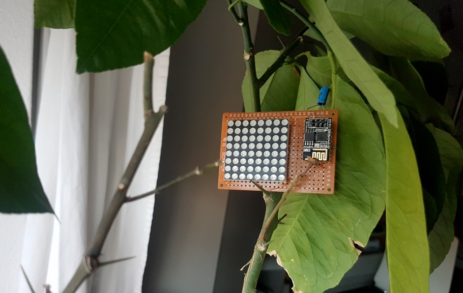
The final product of this hobby project is a tram station board that displays visually how long I have to wait for the next connection to the city by public transportation.
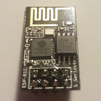
Previously, I have shown how I have assembled a small board with an LED matrix and an ESP8266 at its core. Here, you can find an overview of the software components of the same project. How to install the software on the chip is described in an older post.
Architecture
On the chip, some code is stored in read-only memory (ROM) with features ranging from the MD5 hash function to the 802.11 protocol. The full list can be found here.
Besides the ROM, there is some flash memory available. This is where the custom firmware to be executed can be stored. The source code for that firmware is split into the SDK and the user code, which has been written by myself.
Using the LED matrix effectively
First, let us have a look at how controlling the display works. The LED-matrix has 24 pins which are connected through shift-registers. The entire setup of the hardware is described more detailed in this post.
Interface design
The display consists of 64 LEDs, which I want to control separately. Therefore, a 64-bit integer value can fully describe the state of the display. Well, not quite, actually. Since two different colors on each LED can be turned on and off independently of each other, two such 64-bit values are required.
Here, find the corresponding function signature from the header file led_matrix.h, which acts as an interface towards the main file.
void display_full_matrix(long long yellow, long long red);
All details about controlling the 24 pins in order to display the image defined by the two 64-bit values are then handled in led_matrix.c and thus, well-hidden from the rest of the application.
Alignment with hardware design
When I described the soldering of the components in the previous post, I also mentioned that there might be a problem with the brightness of the LEDs. In fact, when turning on several LED at the same time, all LEDs in a row share the same current. Therefore, the brightness is dependent on how many of them are simultaneously on.
The solution is rather simple. Only turn on one single LED at the time. This implies, that each LED is only on \( {1 \over 64} \) of the time. But with the right speed, looking at it with my bare eyes, I cannot tell the difference at all. However, when recorded by a camera and replayed, some irregular flashing can be spotted easily.
To show the matrix with an arbitrary image being displayed, here is an image that I have taken while debugging.
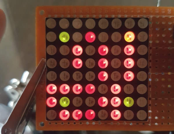
In red, it actually displays the start of an HTTP response, each line representing a character (a byte).
Scheduling
Scheduling is one of the many things that an operating system (OS) on a modern computer takes care of. Basically, when a process finished, the OS decides which process will run next. Or, when one process is waiting for an event, the OS can schedule another process to run in the meantime. Beyond that, the OS may also be able to interrupt and pause a running process when another task with higher priority is ready for execution.
On a small embedded system, there is usually none or only a very limited operating system in place. For the ESP8266, there is an RTOS implementation based on the FreeRTOS kernel available, which does implement basic scheduling among other things. However, for this project¨, I did not really need an OS and I went with the SDK mentioned above only.
Without OS, no scheduling is done. One of the implications is that as long as the user code is running, the entire chip is blocked and no networking tasks can be performed. For that reason, the SDK reference also includes an advice that user code should never run for longer than 15ms.
Then how is the user code run in the correct order? This is possible using timers and task queues. Both features are directly available in the ROM section or the convenience functions defined by the SDK can be used as well.
A timer will trigger an event in a specified interval which will then call a registered function.
A task queue allows adding a function to be called to a waiting queue. Between the tasks in the queue, the chip may decide to run other code instead, like sending a TCP keep-alive message.
Here is a code snippet of the integration of my user code into the SDK’s structure. The full code is available here.
void user_init(){

  // configure GPIOS
  ...

  // setup timer to run user code twice a second
  os_timer_setfn(&some_timer, (os_timer_func_t *)user_loop, NULL);
  os_timer_arm(&some_timer, 500, 1);

  // setup Matrix display loop
  system_os_task(display_matrix, MATRIX_DISPLAY_TASK_PRIO, MATRIX_DISPLAY_LOOP_QUEUE, MATRIX_DISPLAY_LOOP_QUEUE_LEN);
  system_os_post(MATRIX_DISPLAY_TASK_PRIO, 0, 0);

  init_wifi_station();
  init_clock();
}

void user_loop(void *arg) {
  // User code that must be called frequently goes here
}

void display_matrix(os_event_t *e) {
  // turn on and of the LED of the matrix
  // the image to display is defined in a global variable
}

void init_wifi_station() {
  // Initialize the 802.11 connection procedure to the local router
  // register wifi_event_handler
}
void init_clock() {
  // Initialize the NTP connection
}

void wifi_event_handler(System_Event_t *evt) {
  // Handle different events (connected, disconnected, got IP, ...)
}
Fetching live data from the Web
Setting up a connection
To receive data from transport.opendata.ch, several steps have to be done inside the user code. Here is a high-level step-by-step overview.
- Get an IP-Address and establish an Internet connection through the local router and wifi
- Perform a DNS lookup for transport.opendata.ch
- Set up a TCP-connection
- Build and send an HTTP request
- Parse the HTTP response
The time of these operations depends on external circumstances in the network. And as already explained, it is not possible to stay in user code indefinitely. Therefore, we need to register callback functions that will be executed by the chip once the corresponding operation has finished. Inside this callback function, the next step will be triggered and a new callback will be registered.
The user loop
Above code snippet defines the functions user_loop and display_matrix which have been registered to be called over and over again, as long as the system is up and running.
The user loop function decides when a data refresh is due and triggers a new HTTP request accordingly every once in a while.
Inside the function display_matrix, the current image to be displayed on the matrix is computed. It might be a splash screen while the chip is still connecting, or in most cases, the time until the next tram arrives.
To be able to do that, it is necessary to know the current state of the connection inside both of the functions. Remember, the user code has to return after at most 15ms and will be called again later. So, when one of the functions is called, the current state must be checked first and then, depending on that state, some different logic is executed.
Here is a schema of the different states the system can have and which state transitions are possible.
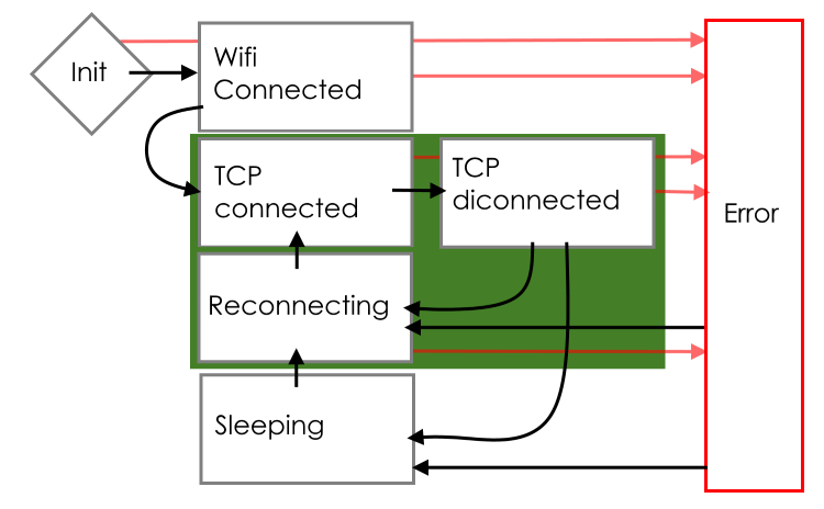
In the states within the green box, the LEDs show the updated time until arrival of the next tram. For most of the time, the system will stay in one of these three states.
In the TCP Connected state, the system has an open connection to transport.opendata.ch and is receiving the updated data. When all information is updated, the connection is terminated and the TCP Disconnected state is entered until it is time to update again.
At nighttime, when no public transportation is available, the Sleeping state is entered in which only very few requests are sent to the server and the display shows a slowly blinking pattern.
If something goes wrong, one of many possible Error states is entered and a debugging error code is displayed through the LEDs. Normally, errors can be recovered by waiting and trying to reconnect at a later point in time.
To make it easy to see what the system is currently doing, the display shows different patterns in different states. For demonstration, this is what it looks like when the chip boots up.
The state Init is too fast to be seen properly but the Wifi Connected state afterward takes about 5 seconds and you can see the corresponding splash screen in the video.
Time
Time is not exactly a trivial issue if its handling is implemented from scratch. The complexity of time zones, daylight-saving time and leap-years combined, creates plenty of opportunities for software bugs.
On the bright side, there is already an NTP implementation on board. I only had to define the remote servers, one of which I have chosen to be my local network router. The SDK then talks to the NTP servers and thereby keeps the system time synchronized.
Reading the time of the next connection, however, is a different story. Although the time format used in the HTTP bodies is fixed to the standard ISO 8601 format, there is nothing really helpful for that on the ESP-chip. So I actually had to parse it from a string to numbers and eventually calculate a UNIX time stamp. This was a bit annoying to do but it is not rocket science, either.
Given a time stamp from the NTP implementation and one for the arrival of the next tram, it is trivial to calculate the number of seconds until that tram arrives and this determines how many LED will be turned on.
The source code
That is all. The entire code is available on my GitHub. Just be warned that this has only been a quick hobby project for me and accordingly the source code is not exactly polished for further maintenance or even teamwork.