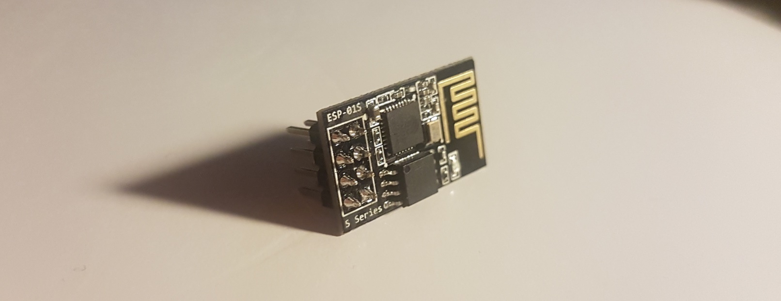
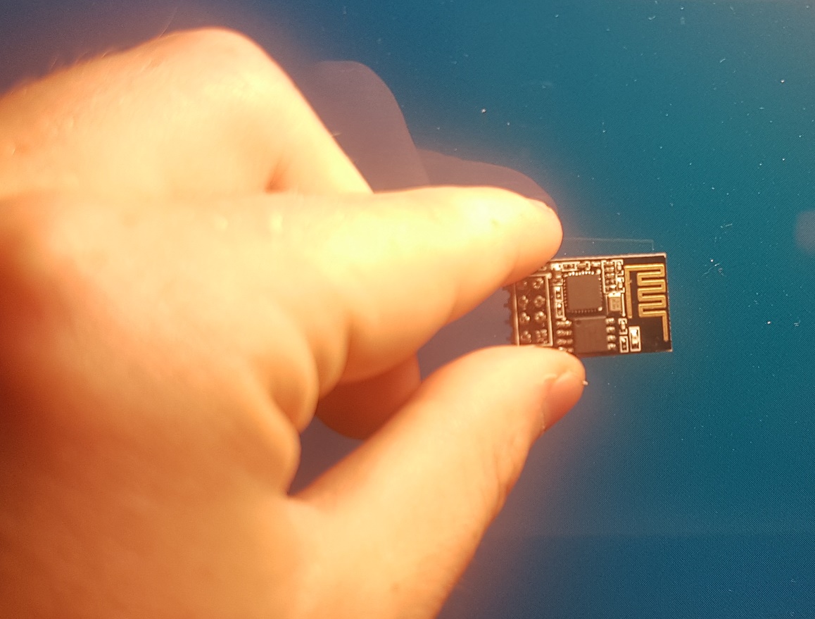
The central processing unit: Merely 5mm by 5mm! The complete module? 14mm by 25mm.
The ESP8266 is a microprocessor natively speaking every protocol required to connect to the World Wide Web through a local WiFi network. In this post, I am writing about the ESP-01S module, one of the most common modules using this microprocessor.
The picture above already shows the entire ESP-01S module, only the lack of an energy source is stopping it from connecting to the Internet. One such chip is available below $3 even as a private person. And all the software required to program it is openly available!
What can be built with it?
The project possibilities are endless. For instance, the module is small enough to be the heart of an amateur smartwatch. Another idea would be to attach it to a security camera and transmit the recordings to a server. Or you could even go as far as building an intelligent robot which uses the ESP-01S to connect to the Internet. The actual computational power could then be externalized and thus the robot itself is light and only required minimal energy batteries.
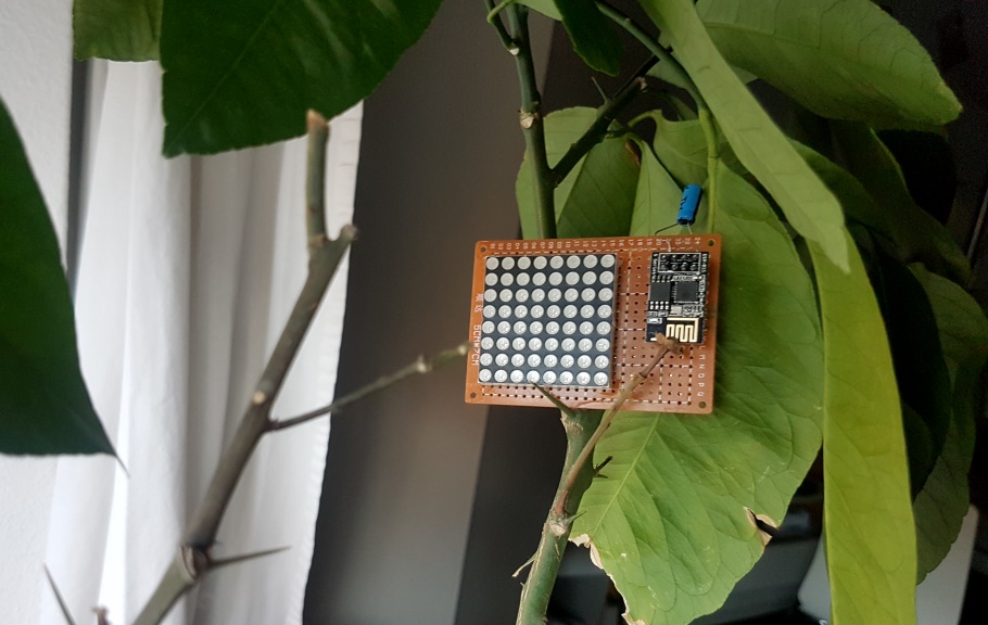
To keep it simple, I decided to control an 8x8 LED matrix and display some data from the web on it. For now, it displays how long it takes until the next electric tram leaves from my house to the city. And the data is coming live from the Internet, calculating in current delays. A full description of this project will follow in other posts later on. In this post, I want to first cover the basics of the chip only.
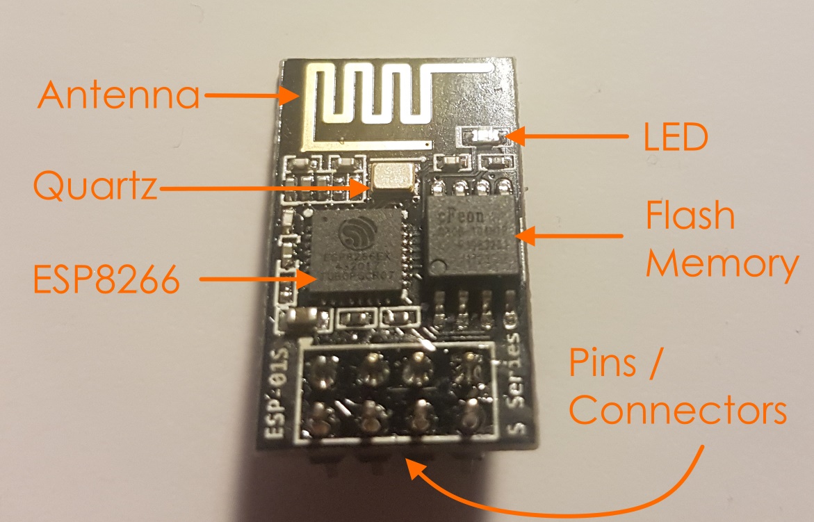
The layout of the ESP-01S
The processor
At its core, the module has a 32-bit RISC processor, the ESP8266 which has been designed by the international company Espressif Systems with headquarters in Shanghai.
The data sheet tells us what exactly is inside of it. At a rate of 80MHz, it computes the protocols 802.11 (also known as WiFi), IPv4, TCP, and HTTP, among other things. These protocols together are all we need to fetch data from an arbitrary website. Or alternatively, the chip can also act as WiFi station which allows us to directly connect to it from a smartphone or laptop, without the need of a WiFi-Router.
But a microcontroller would not be complete without some pins to send out and receive electrical signals. The ESP8266 has 32 pins in total, whereas 16 of them are general-purpose input/output pins (GPIOs). These are most interesting to us since we can use them to control LEDs, motors, or whatever our project requires. The other 16 pins are designated to specific tasks and I will not explain them further right now.
The module
Given that the processing unit by itself can only do computations and is therefore not impressively useful, let us have a look at what else the ESP-01S module brings along. The most important parts are:
- 1MB flash memory to store software on it
- A WiFi antenna
- A crystal oscillator (quartz) to time the frequency on the UART channel
- Connectors to the critical pins:
- 3V3: Current input
- GND: Ground / Current output
- EN: Is used to enable different modes of the chip
- RST: Can be used to reset the chip.
- RX: UART receiver (Can also be used as a GPIO)
- TX: UART transmitter (Can also be used as a GPIO)
- IO0: GPIO
- IO2: GPIO
Only with these additional parts, the microprocessor becomes a true microcontroller which can be reprogrammed and is able to communicate with its environment in different ways.
As a side note, as you can see this particular module only uses 4 out of 16 available GPIOs of the ESP8266. And also for the other 16 pins, not all of them are connected. Of course, some of them are used, for example, to access the flash memory, but others are simply not accessible through this module. However, all the fundamental requirements are met and with the reduced feature set the chip remains small and compact.
Programming the ESP8266
In a next step, I want to describe how user software can be run on the ESP8266. First, we have to compile our program code into binaries specific to the processor family. Afterwards, the binaries must be written onto the flash memory, also known as flashing.
Writing and compiling code
Today, there is a good number of different ways to write code for the ESP8266 family. For instance, one could make use of the NodeMCU platform and write scripts in Lua. And thanks to this cool project, even the popular Arduino IDE can be used.
Myself, I decided to stick to good old C for my projects. Espressif has provided a nice SDK with a decent documentation which really leverages this approach and lets me directly access all features of the microprocessor.
Setting up the toolchain
To set up my development environment, I completely relied on the ESP Open SDK project. After following the steps described there, I just had to fix some conflicts in the versions of preinstalled software and eventually correct some permissions of my file system. And now I have a fully functional toolchain to compile C program code to ESP8266 binaries.
As it is often the case when working with C, a Makefile helps me to remember the long commands to compile and link everything correctly. Here, the command hiding behind make is as follows:
xtensa-lx106-elf-gcc -I. -mlongcalls -I/home/jakob/esp-open-sdk/sdk/include     -c -o blinky.o blinky.c
xtensa-lx106-elf-gcc -T/home/jakob/esp-open-sdk/sdk/ld/eagle.app.v6.ld -L/home/jakob/esp-open-sdk/sdk/lib  blinky.o  -nostdlib -Wl,--start-group -lmain -lnet80211 -lwpa -llwip -lpp -lphy -lc -Wl,--end-group -lgcc -o blinky
This compiles my first test program blinky.c and created the binaries fitting to the ESP8266.
Flashing
Having the binaries ready, we still have to write them onto the flash memory of the module. Here are some challenges I faced while trying that for the first time and how I resolved them.
Connecting to the computer
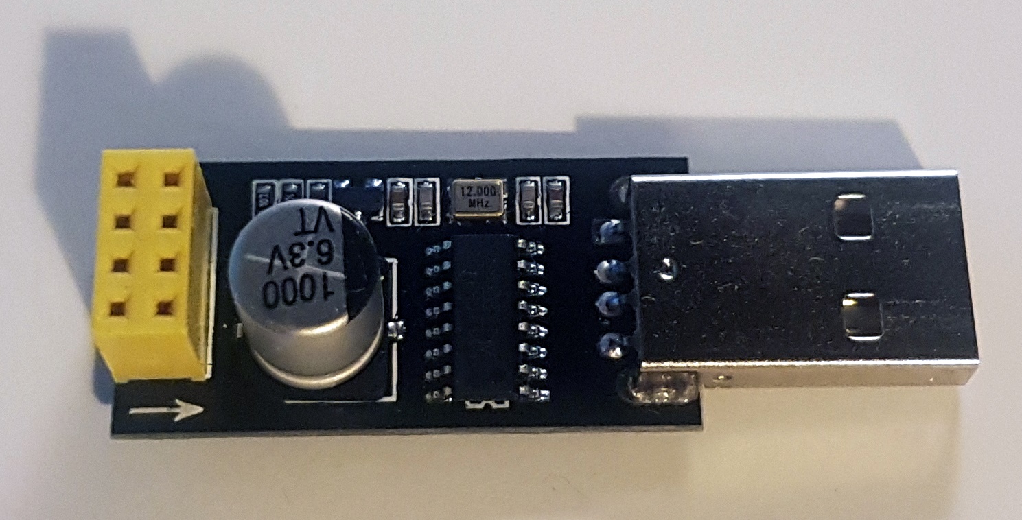
This USB to TTL adapter physically fits perfectly to the ESP-01S. When I put the chip on the adapter and plug in the adapter to my laptop, the chip starts up without any issues and I can even receive and send data using a program like PuTTY. If you plan to buy such an adapter, make sure you get one with a 3.3V voltage on the power pin as well as on the data pins. The first adapter I bought was transmitting and receiving data on 5V which makes it unusable for the ESP8266 unless you do some extra conversion in between.
Triggering the bootloader
Simply plugging in the chip with above adapter will always start the chip in the normal mode, where it starts running the software on the flash memory immediately. However, to flash the chip, we need to start the bootloader instead. To do that, the following signals must be applied to the pins on startup:
| Pin | Value |
|---|---|
| EN | + |
| IO0 | - |
| IO2 | + |
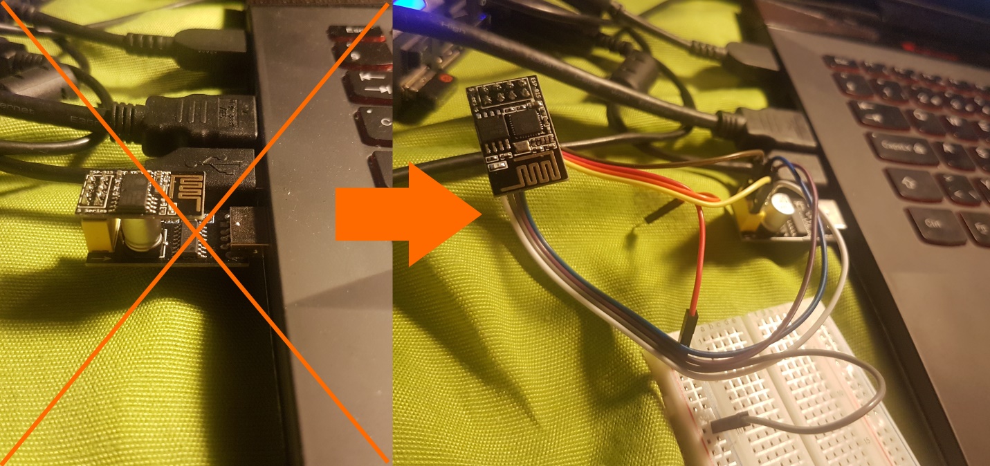
To achieve this configuration, I took an external power source and used it to apply a positive voltage to both the EN and IO2. The IO0 seems to be already LOW on the adapter, so I did not have to change that.
With the external power source, this is how the flashing position looks like for me:
Being connected to my laptop, the flashing may begin. I can recommend the tool esptool.py for that. In the case where everything works as intended and the flasher can communicate successfully with the chip, it looks like this in the terminal:
esptool.py write_flash 0 blinky-0x00000.bin 0x10000 blinky-0x10000.bin
  esptool.py v1.2
  Connecting...
  Auto-detected Flash size: 8m
  Running Cesanta flasher stub...
  Flash params set to 0x0020
  Writing 32768 @ 0x0... 32768 (100 %)
  Wrote 32768 bytes at 0x0 in 2.9 seconds (91.9 kbit/s)...
  Writing 200704 @ 0x10000... 200704 (100 %)
  Wrote 200704 bytes at 0x10000 in 17.4 seconds (92.2 kbit/s)...
Done! Our user software is on the chip and being executed right now.
In some of my next posts, I will show further steps of my project with the ESP-01S and also present some program code that runs on it.