The time until the departure of the next tram always displayed on my room's wall. How to build the hardware for it?
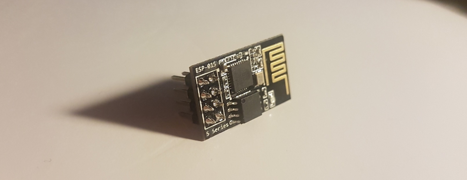
In my last post, I have introduced the ESP-01S module and I showed how to program the integrated ESP8266. Now, I want to talk about a project I have realized, using that technology.
This post covers the design thoughts behind the hardware. The software part, including all code running on the chip, is postponed to the next post.
What we are aiming for
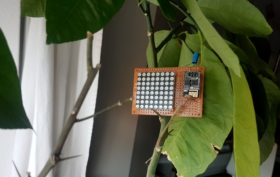
Before losing ourselves in details, let us check out how the fully working construction looks like.
The LED matrix displays a timer. Each LED that is on represents 10 seconds until the arrival of the next tram leaving towards the city center. The installation of this gadget in my room allows me to always leave home with minimal waiting time for public transportation.
To keep the display coherent with reality, the ESP8266 continuously checks the live timetable provided by Open Data.
Shopping list
- ESP-01S module
- 8x8 LED matrix
- 1x empty DIY circuit board
- 3x 74HCN595 8-bit shift register
- 47Ω and 3.3kΩ resistors
- 0.1 μF electrolyte capacitor
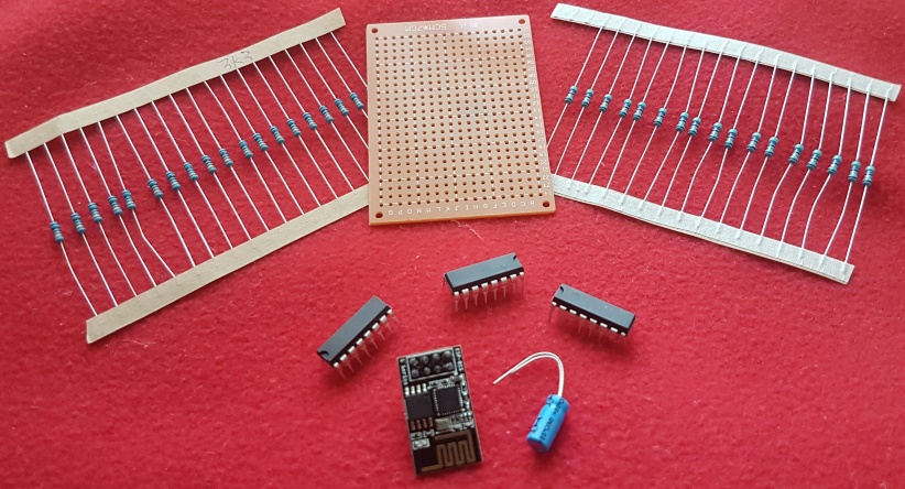
On the picture, we see all components with the exception of the LED matrix. However, the shift registers that I have actually used are 74HCN595D, whereas we see the substantially bigger 74HCN595N on the picture. Functionally, they are equivalent. And the reason I have used the smaller ones is quite simple, I did not own the larger model back then when I started. But if you can choose, always go for the larger registers. They are much easier to soldier by hand and the distance between the pins perfectly matches the standard DIY circuit boards.
Positioning the major pieces
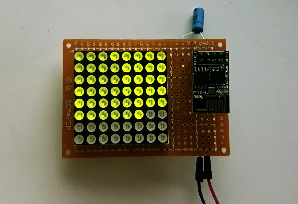
Since this is a technical DIY project, I decided that it is NOT my goal to make it look beautiful. Especially not by trying to hide all technical parts. Those should be nicely arranged (at least on the front) but I am okay with people seeing right into the heart of the item at hand.
That leaves us with the ESP-01S visible right next to the LED matrix. The rest found its place on the backside, whereas the capacitor peeks around at the top.
But the real challenge takes place on the backside, where we should connect the GPIOs of the chip to the LED matrix. The twist: There are only 4 GPIOs on the ESP-01S to control 24 pins on the matrix (8 rows, 8 columns(red), 8 columns(yellow)).
The standard solution here is using shift registers. With only 3 GPIOs, virtually any number of registers can be controlled, if set up in series properly. Each of the registers then has 8 outputs that can be used to control, among other things, LEDs. How to use them exactly, I am not going to explain right here, there is already plenty information about it on the web and the datasheet of the specific model I have used can be found here.
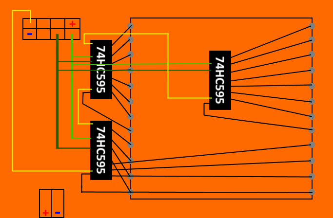
Here is the circuit I came up with for the connections between the main components. In light green, we have the source clock (SRCLK). In darker green, the register clock (RCLK) and in yellow the path of the bits, as they are shifted through the registers. Each of the colors takes one GPIO of the ESP-01S.
Requirements on current and power
To make sure nothing is burned, we will also need to add some resistors.
The first limit is given by the maximally allowed current of 70mA on each register. One possible design would use one resistor at each register output, thereby regulating each pin to \( {70 \over 8}mA \) . This will also make sure that the LEDs always shine with the same intensity, no matter how many of them are on simultaneously.
Unfortunately, the described method requires 24 resistors, which all take up space and time to be physically integrated. This was enough for me to dismiss the idea and rather put one resistor in front of each register, immediately dividing the workload by 8. How we work around the problem of an unequal brightness of the LEDs using software only, I will explain in the next post in the series.
With the new idea, what values of resistors are required? The operating voltage sits at 3.3V and the desired current at 70mA. Using Ohm’s law we compute:
\[ R = {V \over I} = { 3.3V \over 0.07A} = 47.14\Omega \]
Theoretically, this is the smallest safe-to-use resistor value. But as I happened to have 47Ω resistors at hand, I felt like I could take the risk.
The other limiting factor is the maximum power of the resistors, in my case 0.25W. To calculate the limit here, first, we derive the relationship between power and resistor values.
\[ P = {V \times I} = {V \times {V \over R}} = {V^2 \over R} \]
And then we can solve for R to get the smallest safe resistor value. \[ R = {V^2 \over P} = { 3.3V \times 3.3V \over 0.25W} = 43.56\Omega\]
Awesome, the previously chosen 47Ω resistors also meets this requirement and we can rest assured that nothing in the circuit will burn.
Considering what other requirements we could find in the circuit, there are only the LED-matrix and the ESP-01S module left. For my LED matrix, I could not find a fitting data sheet, so I do not know the exact tolerance. But by looking at the specifications of similar LED matrices, it seems that with 3.3V I am already on the safe side. And to speak about the ESP-01S, its pins are really only used to activate/deactivate the registers, not to power them, so we do not have to be concerned to ever reach the current limit of 12mA there.
Power circuit
After presenting some of my considerations for the power circuit, here is the schematic for it.
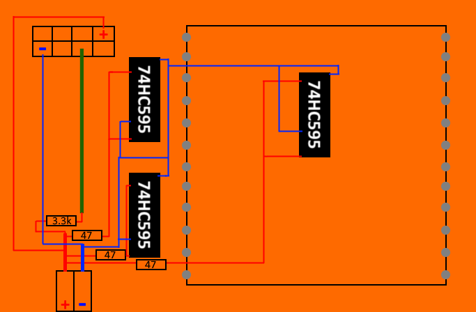
Beyond the single connections of the components to plus and minus, we find some additional lines on the graphic, which are also required to properly enable the registers. In particular, all OE pins of the registers must be connected to a negative voltage, thereby enabling the output pins, and the reset pins RST should touch a positive voltage. And that is where all those additional connections on the graphic come from.
One more line can be found in above circuit, the connection between the positive source and the dark green line, through a 3.3kΩ resistor. The reason we need a connection at all goes back to my explanation in the previous post because the ESP-01S has sharp requirements on the start-up configuration, or it will not run the programmed code. In this case, the IO0 must be positively charged. But if we just connect it to the source directly, we will not be able to use it as an output pin as it is hard-wired to that HIGH value from the source. Using a resistor as shown will circumvent this, by weakening the HIGH signal enough that the output of the chip can outweigh it.
Decoupling capacitor
If a number of electrical components are connected like this, interference between different parts will occur. Sometimes, it is weak enough to not have an impact on the behavior of the complete system. Other times, engineers and hobbyists are less lucky.
After my first round of soldering, I found the chip rebooting randomly and the LEDs flickering occasionally. Some of it has clearly been caused by sloppy soldering and I could fix it by resoldering some connections. But still there seemed to be some instability left.
One way of reducing instabilities on the circuit is to add capacitors of the right capacitance and material at the right place in the circuit, which I also tried. However, I am neither formally educated nor experienced with the applications of such capacitors, so take these paragraphs with an appropriate grain of salt. My understanding of the topic basically relies on some hours of research on the web. One of the most concise summaries about the different usages of capacitors I found on capacitorguide.com but it is by far no the only high-quality source I have found about the topic.
So, after my research, I ended up using an electrolyte 0.1μF capacitor as close as possible and in parallel to the chip. The idea is that it decouples the main chips power consumption spikes from the rest of the circuit.
I cannot clearly say that a capacitor is required for the sketched circuit to work. It did already work relatively well before I applied one and I have not done any isolated experiments to prove that the capacitor has a positive effect. But I did add it anyway and now with mostly clean soldering, I find nearly no irregularities at all on my little station board.
Result
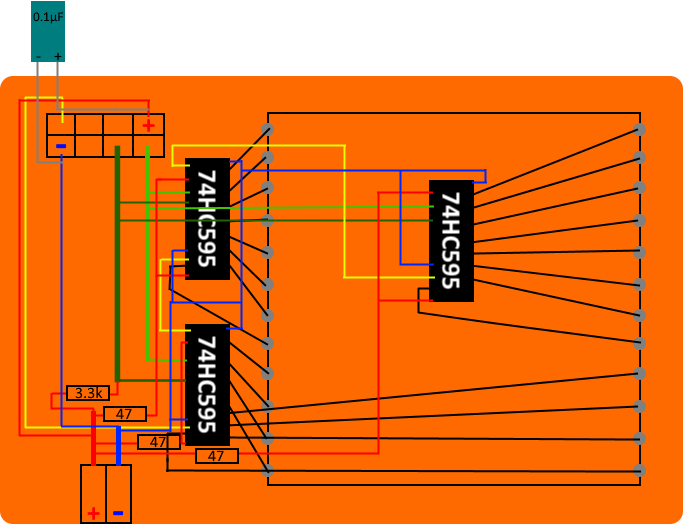
To sum up it all up, here is the complete plan for what I have soldiered by hand for this project.
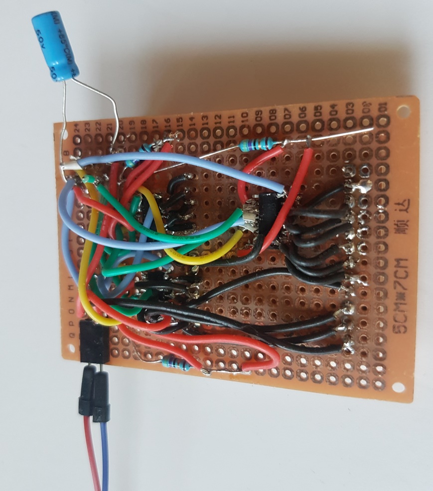
Soldering all of it on a small area was not even as hard as I expected, given this has been pretty much my first soldering experience. Admittedly, it took me some time to find all faulty soldered spots but finally, I could detect and erase them all.
Still, the presented view to the backside of the board is, well, messy to say the least. It is very clear that no professional has been involved in that work. Nevertheless, I am happy and even a bit proud that everything is now working anyway.
In the next post of the series, I will present the software running on the chip which will make the chunk of electronics useful.